This update brings new tools for importing designs from KiCAD, editing multiple components at once, simplifying your diagrams, and generating manufacturing documentation.
New Features
KiCAD PCB and Schematic Import
Import connectors directly from your KiCAD projects:
- Multi-file support: Upload KiCAD PCB files (.kicad_pcb), schematic files (.kicad_sch), and netlist files (.net) together
- Automatic connector detection: Identifies connectors by reference designator prefixes (J, CN, CON, P, X) and common footprint patterns
- Pin-to-signal mapping: Netlist files provide accurate signal names for each pin connection
- Footprint parsing: Extracts manufacturer, series, pin layout, and pitch from KiCAD Library Convention footprint names
- Multi-sheet schematic support: Tracks source sheets for hierarchical designs
- Configurable label formats: Choose how pin labels are formatted (number-signal, signal-number, etc.)
To import from KiCAD:
- Click the Data Import/Export button in the top toolbar and select Import from KiCAD
- Drag and drop your KiCAD files (.kicad_pcb, .kicad_sch, .net)
- Configure reference designator prefixes if needed
- Review detected connectors
- Configure pin label formats
- Add selected connectors to your harness
Tip: Include the netlist file (.net) for accurate signal names on each pin. Without it, pin names will fall back to schematic definitions or numbers.
Update — June 2026: the in-browser KiCAD file import has been replaced by the Splice CAD KiCad plugin, which exports connectors straight from KiCad into a Splice Project in one click.
Coming Soon: Automatic mating connector matching will search our parts database to find compatible mating connectors based on manufacturer, series, pin count, and pitch.
Bulk Property Editor
Edit multiple components, wires, and cables simultaneously with the new Bulk Property Editor panel:
- Components tab: Edit manufacturer, MPN, and custom designators for multiple connectors at once
- Wires tab: Bulk edit wire color, stripe, AWG, signal labels, and visibility settings
- Cables tab: Edit cable manufacturer, MPN, and length for multiple cables
- Auto-renumber: Renumber component or cable designators based on position (left-to-right or top-to-bottom)
- Pending changes preview: Review all edits before saving
- Undo/Redo support: All bulk edits are tracked in the command history
Access the Bulk Property Editor by clicking the edit icon in the floating toolbar or pressing E.
Collapse Empty Pins and Cores
Simplify your harness diagrams by collapsing unused pins and cable cores:
- Collapse empty pins: Hide unconnected pins on a connector to reduce visual clutter
- Collapse empty cores: Hide unused cable cores on multi-core cables
- Collapse/Expand all: Use the bottom toolbar menu or right-click context menu to collapse or expand all components at once
- Per-component control: Right-click any connector or cable to toggle collapse state individually
- Undo/Redo support: Collapse operations are fully tracked in command history
Collapsed connectors show only pins with active connections, making complex harnesses much easier to read and navigate.
Wire Bundle Visibility Controls
Control the visibility of entire wire bundles for focused editing:
- Hide bundles: Temporarily hide wire bundles to reduce visual clutter while working on specific areas
- Compact mode: Toggle bundles between full and compact visual representations
- Bulk visibility: Use the Bulk Property Editor to toggle visibility for multiple bundles at once
- Real-time preview: Visibility changes apply immediately without waiting for save
Cut List Export
Generate manufacturing cut lists that consolidate wire and cable requirements:
- Wire consolidation: Groups wires by MPN and manufacturer with total length calculations
- Individual lengths: Shows length distribution (e.g., "3 x 200mm, 2 x 350mm") for cutting planning
- Cable support: Includes multi-core cables with total length across all connections
- Bundle labels: Shows which wire bundles use each wire type
- Multiple formats: Export as CSV, Excel (XLSX), or PDF
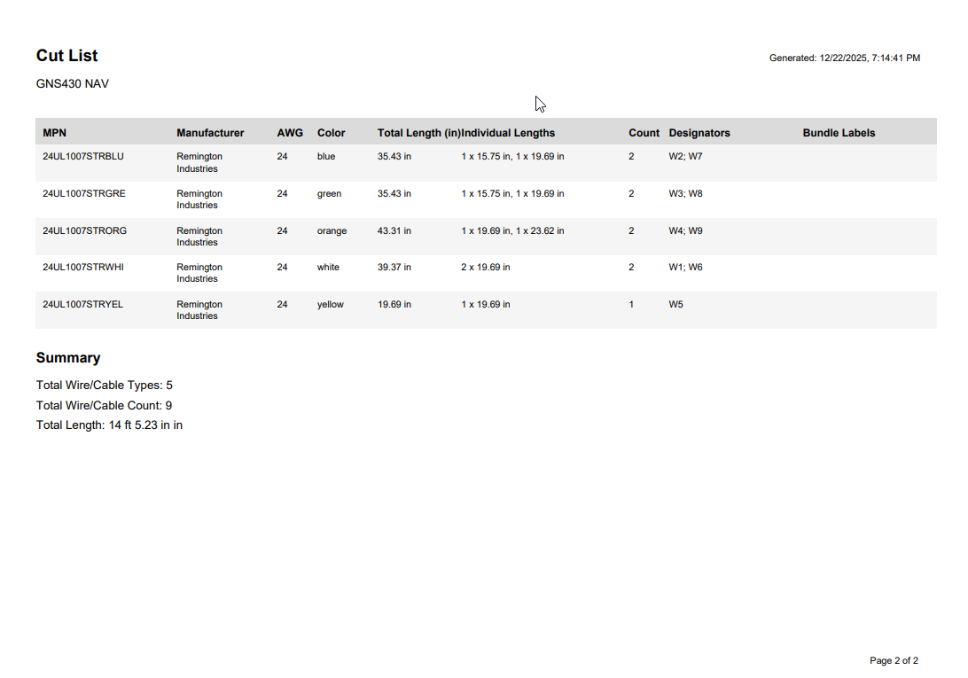
Access cut list exports via Download & Upload > Cut List.
Connection Table Export
Export detailed connection tables showing every wire and cable connection:
- Grouped by bundle: Connections organized by wire bundles (e.g., "Bundle X1 | X2") and cables (e.g., "Cable C1")
- Full connection details: From/To pins, signal labels, wire color, AWG, and length
- Bundle labels: Shows bundle labels at each connection end (e.g., "TO POWER SUPPLY")
- Cable cores: Lists all cable cores including shield connections
- Flying leads: Displays termination type for unterminated wires
- PDF export: Professional multi-page PDF with automatic page breaks and continuation headers
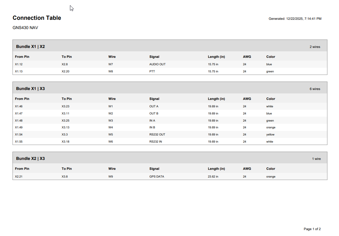
Connection tables are included in the Cut List PDF export.
Multi-Page PDF Engineering Drawings
Cut lists and connection tables are now integrated into the single and multi-page PDF engineering drawings:
- Connection table pages: Detailed wire-by-wire connection information grouped by bundle
- Cut list pages: Consolidated wire requirements with totals and length distributions
- Dynamic row heights: Text wraps automatically to show full designator lists without truncation
- Page overflow handling: Tables automatically continue across pages with "(continued)" headers
What's Next
Short Term Goals
- Automatic mating connector matching for KiCAD imports
- Enhanced WireViz YAML import compatibility
- Include connector graphics in WireViz YAML exports
We're tracking bugs, feature requests, and improvements on GitHub. Please share your feedback!