This update introduces Layout View, a documentation system for creating manufacturing-ready assembly drawings, BOMs, and technical specifications.
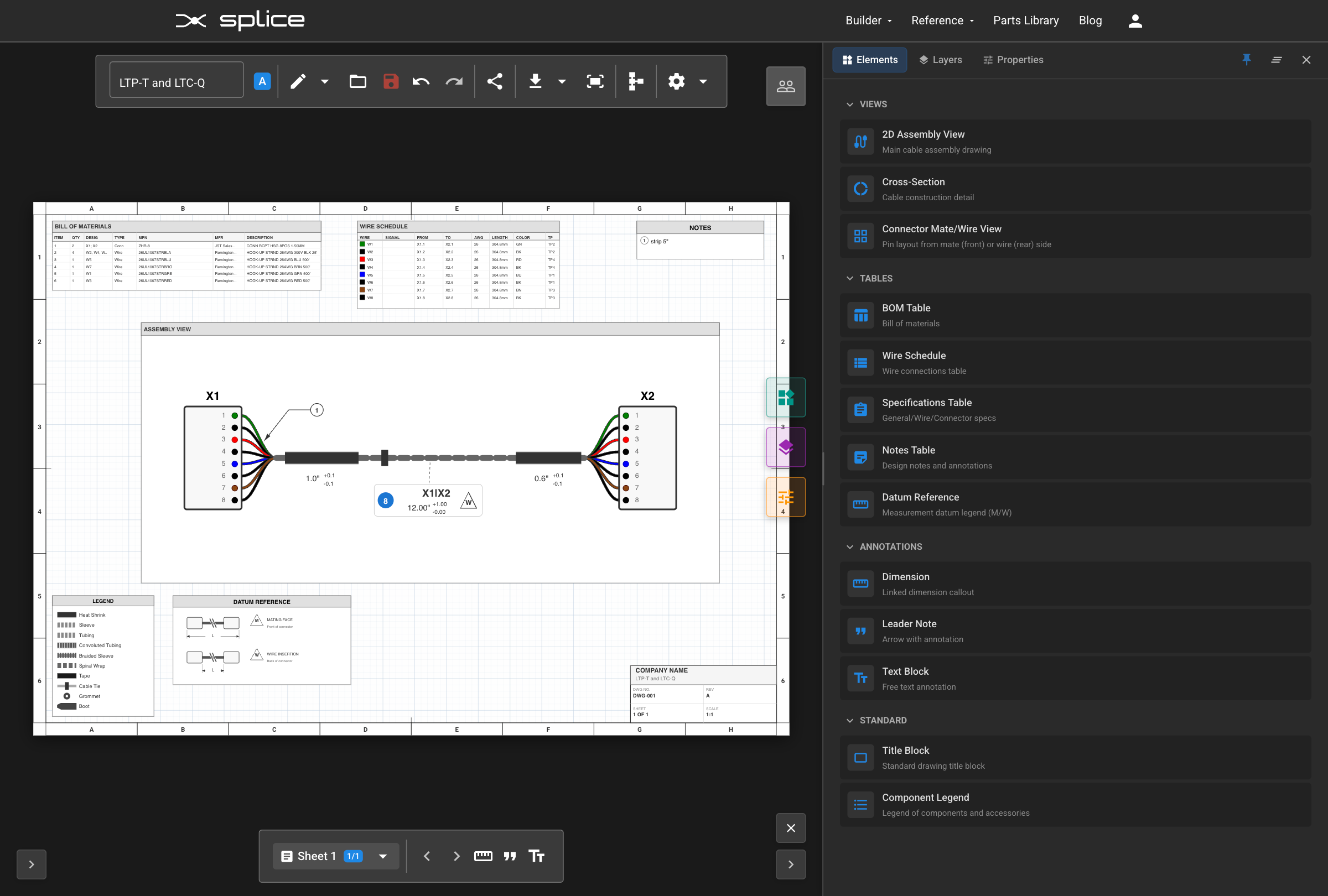
Introducing Layout View
Layout View adds a complete technical documentation platform to Splice CAD. Create multi-page drawing packages without leaving the application.
From Schematic to Documentation
Layout View works hand-in-hand with Schematic View:
- Design in Schematic View — Place components, route wires, and define connections. This is the source of truth for your design data.
- Switch to Layout View — Click the ruler icon in the toolbar. Your schematic data flows automatically into documentation elements.
- Build your drawing — Add Assembly Views, BOM tables, and annotations. These elements pull live data from your schematic—change a wire gauge in Schematic View, and your Wire Schedule updates automatically.
- Export for manufacturing and assembly — Generate PDFs ready for the production floor.
Multi-Page Drawing Packages
Create unlimited drawing sheets with standard page sizes:
- Letter, A4, A3, A2 in landscape or portrait orientation
- Per-sheet text scaling (50%–200%) for readability
- Page templates: Blank, Assembly, Cable Spec, Connector Spec, Requirements
- Professional border styles with zone references (A-Z grid)
Element Library
The Element Library contains 14+ element types organized into four categories:
Views
- 2D Assembly View — Main cable assembly drawing with interactive elements
- Cross-Section — Cable construction and bundling detail views
- Connector Mate/Wire View — Pin layout diagrams from mate (front) or wire (rear) side
Tables
- BOM Table — Bill of materials with automatic population from harness data
- Wire Schedule — Detailed wire connection table
- Specifications Table — General, wire, and connector specifications
- Notes Table — Design notes and annotations
Annotations
- Dimensions — Linked dimension callouts with configurable display
- Leader Notes — Arrow with annotation for highlighting specific features
- Text Blocks — Free text annotations
Standard Elements
- Title Block — Drawing title block with company info, drawing number, revision
- Component Legend — Legend of components and accessories used in the design
Assembly View Capabilities
The 2D Assembly View is the centerpiece of your drawings:
- Move connectors by dragging them within the view
- Reshape cable paths — Double-click on a cable to enter Bezier edit mode, add control points, and create custom curves
- Drag accessories (heat shrink, tubing, labels) along cable paths to reposition them
- Resize accessories by dragging the start/end handles
- Connector shapes are automatically detected from part specifications
How to Access
Click the ruler icon in the Harness Builder toolbar to switch to Layout View.
View the Layout View Tutorial →
Splice Components Library
We've added a library of splice components for inline wire connections. Splices connect wires together mid-harness, representing branching points, junction connections, and various wire joining techniques.
Add from Components panel: Select the "splice" category in the Components panel and add to the canvas.
Insert inline on existing wire: Right-click a wire → Insert Splice. The wire is automatically split and the splice is positioned between endpoints.
Bundle Accessories
Add accessories to your cables and bundles directly in Schematic View. Select a cable or bundle and open the Bundle Properties panel to add:
- Heat Shrink Tubing — Specify diameter, length, color, and material
- Corrugated Tubing — Split or non-split protective conduit
- Braided Sleeving — Expandable mesh protection
- Zip Ties — Cable management at specified intervals
- Tape Wraps — Spiral or longitudinal wrapping
- Labels — Identification markers at any position
Accessories are included in the BOM and visualized in Assembly Views in Layout View.
Join Our Discord Community
We've launched a Discord server for the Splice CAD community! Connect with other users, get help with your designs, share feedback, and stay up to date on new features.
Join here: discord.gg/MFM23eV2
- Get help and share designs
- Feature requests and bug reports
What's Next
Short Term Goals
- Enhanced WireViz YAML import compatibility
- Additional splice and terminal templates
- Connector graphics in WireViz YAML exports
We're tracking bugs, feature requests, and improvements on GitHub. Please share your feedback on GitHub or join our Discord!