This update introduces Projects — a new layer on top of the Harness Builder for designing electrical systems from the top down. In Project Mode, you design your system's connectivity first without selecting parts upfront. When you're ready, generate one or more harness assemblies that open in Harness Builder for detailed work. Projects are in beta now. This update also includes several Harness Builder improvements: box select, bulk edit, and wire anchor enhancements.
We're looking for early testers and feedback. Reach out on Discord or email us at info@splice-cad.com to join the beta. Read the Project Mode documentation to get started.
Projects & Project Mode (Beta)
The Harness Builder is focused on individual harness assemblies — it doesn't have a concept of the broader system. There's no way to group connectors as a single device, no way to document how connectors mate, and no way to describe physical bundle routing. Project Mode adds that system-level layer: design your full connectivity with device groups, mates, signals, and bundle topology, then generate one or more assemblies when you're ready to get specific. Or stop at the plan and export PDF schematics, BOMs, and netlists directly.
Design Top-Down
Start with what devices exist, how they connect, and what signals flow between them. The plan canvas has two views: Layout for physical topology and Schematic for individual conductors. Generate assembly schematics when your design is ready.

Stay Generic Until You're Ready
Add components without specifying parts. Pin counts grow as you add connections. Assign parts from the library when the design stabilizes — not before.
Model Devices
Device Groups represent multi-connector devices like PCBs or DIN rail assemblies. Mates document how connectors physically pair. Signals classify what each conductor carries (VDC, GND, CAN_H) with color-coded badges that propagate across the net.

Handle Complex Routing
Branch Points model junctions and bus topologies. Distinguish between pass-through conductors and physical splices. Build power distribution buses, fan-outs, and tree topologies. Splices are BOM-tracked.

Multi-Page Organization
Break large systems across multiple pages while maintaining a single connected plan. Organize by subsystem — power, communications, sensors. Navigate with the tab bar or keyboard shortcuts (Ctrl+PageDown/PageUp).
Generate Assemblies
Select a subset of components, bundles, and branch points, then generate an assembly that opens in Harness Builder. Generate multiple assemblies from one plan. Sync pushes plan changes to existing assemblies. Auto ferrules are created at termination-to-termination connections.

Box Select & Group Repositioning
Select multiple elements on the canvas with box (marquee) selection, then move them as a group.
Selection Modes
Box select supports two selection modes depending on drag direction:
- Window select (drag right) — Only elements fully enclosed by the selection rectangle are selected.
- Crossing select (drag left) — Any element that touches or is enclosed by the selection rectangle is selected.
Modifier Keys
- Shift or Ctrl/Cmd — Add to the current selection
- Alt/Option — Remove from the current selection
- No modifier — Replace the current selection entirely
Group Drag
After selecting multiple elements, drag any selected element to reposition the entire group. Relative positions between elements are preserved during the move.
Bottom Toolbar
When elements are selected, a bottom toolbar appears with quick actions for the selection — delete, align, distribute, and more.
Bulk Edit & Bulk Connect
The Bulk Edit panel lets you view and edit properties across multiple components, wires, and cables at once.
Contact Assignment
The Components tab now lets you assign contacts across multiple connectors at once. Switch to the Contacts view to see pins grouped by AWG — select a compatible contact type and apply it across multiple pins or components simultaneously.

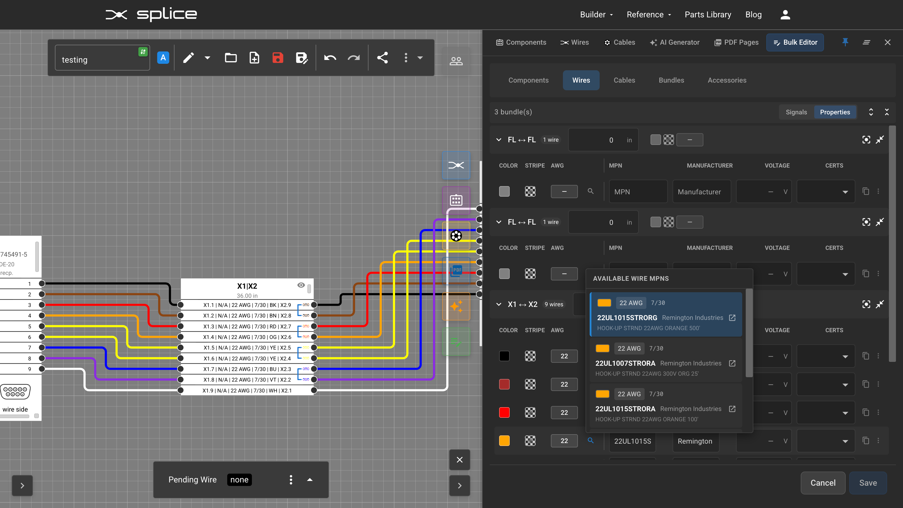
Wire Part Selection
The Wires tab lets you select and assign wire parts across multiple wires at once — set signal labels, wire types, and twisted pair groupings in bulk.
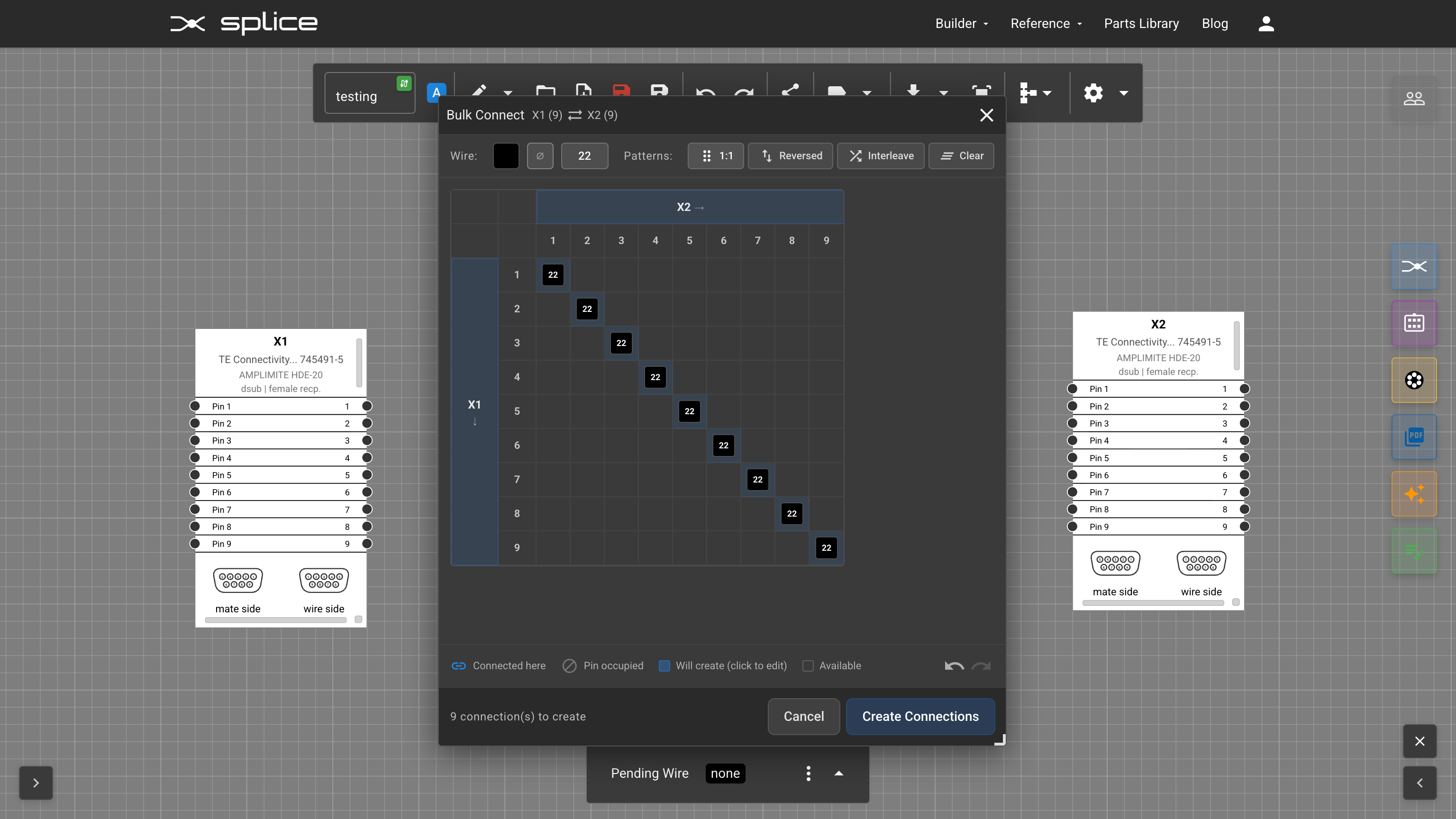
Bulk Connect
The Bulk Connect dialog has been updated with a connection matrix for fast wiring with common patterns:
- 1:1 — Connect pins in order (pin 1 to pin 1, pin 2 to pin 2, etc.)
- Reversed — Connect pins in reverse order
- Interleave — Alternating pin connections for specific wiring patterns
Wire Anchor Improvements
Wire anchors give you manual control over wire routing by adding control points along wire paths. This update improves how anchors work with selection and layout tools.
Box Select Integration
Wire anchors are now fully integrated with box select. Select anchors alongside connectors and other elements, then reposition everything together as a group.
Distribute Function
Select multiple wire anchors and use the Distribute function to space them evenly — useful for creating clean, parallel wire runs.