Component Creator
Overview
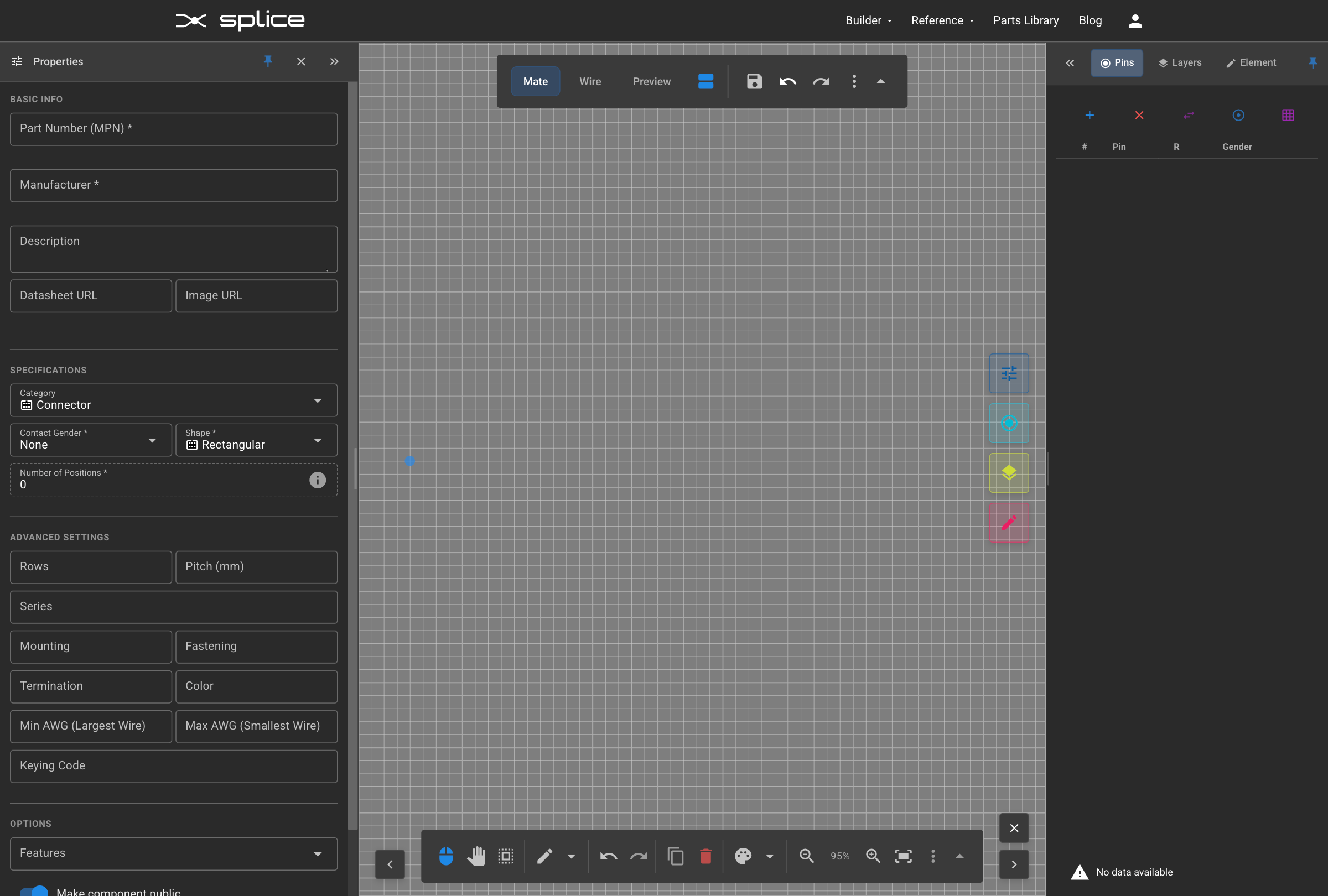
Connector Creator Interface
The Connector Creator provides a visual SVG editor for designing custom connectors. The interface is divided into three main areas:
- Left Panel: Basic properties, specifications, and pin configuration
- Center Canvas: SVG editor for drawing your connector
- Tab Navigation: Switch between Mate Side, Wire Side, and Preview
Getting to the Creator
Navigate to the Connector Creator by clicking App → Component Creator in the top navigation menu.
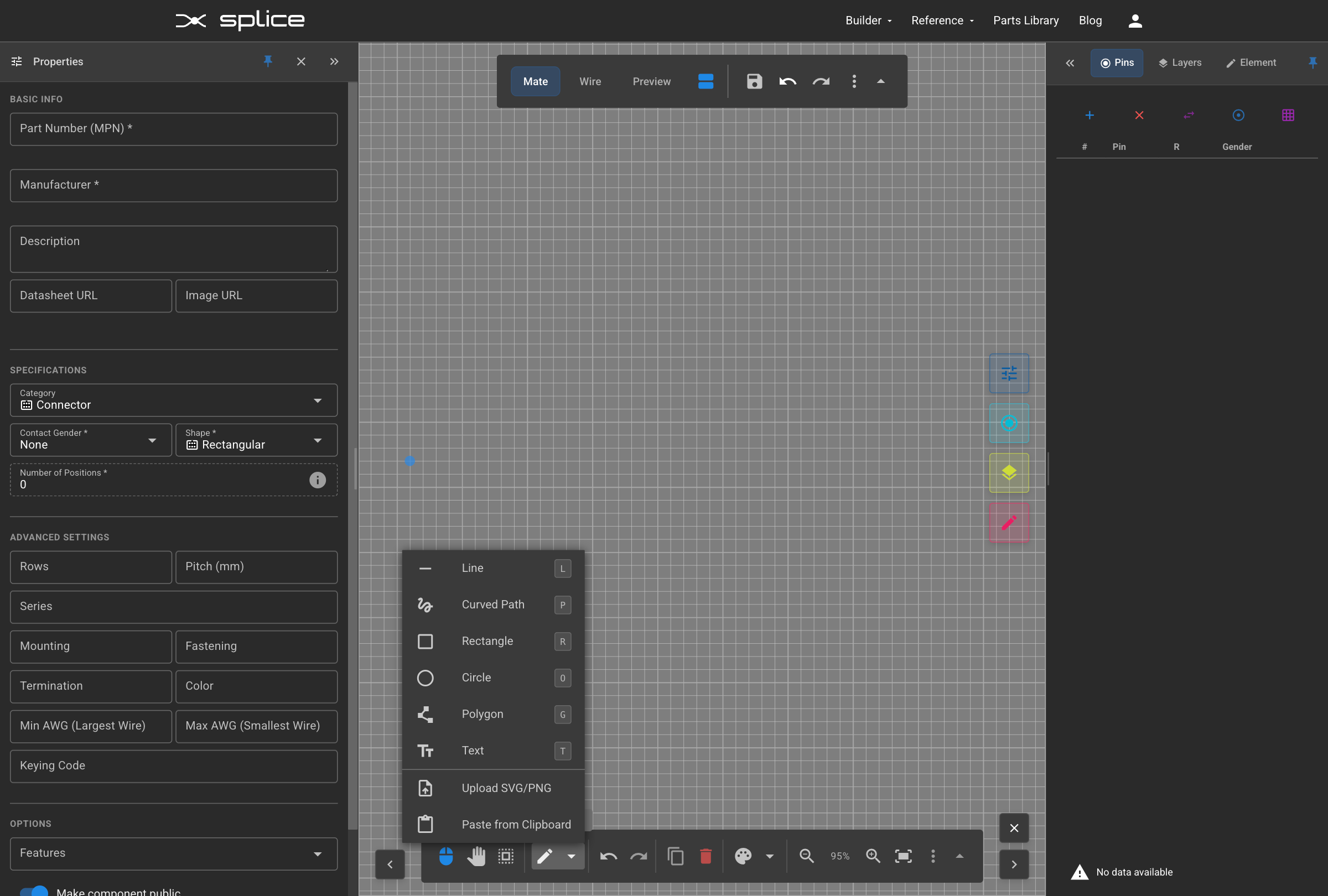
Importing Graphics
Alternative Workflow: Import Existing Designs
Instead of drawing from scratch, you can import existing SVG or PNG graphics as a starting point:
SVG Import
- Click the "Upload SVG or PNG" button in the toolbar
- Select an SVG file from manufacturer datasheets, CAD exports, or design tools
- All styling, colors, and shapes are preserved
PNG/Raster Image Import
- Click the "Upload SVG or PNG" button in the toolbar
- Select a PNG image file
- The image is embedded as a base64-encoded element
- You can position, resize, and layer the image with other elements
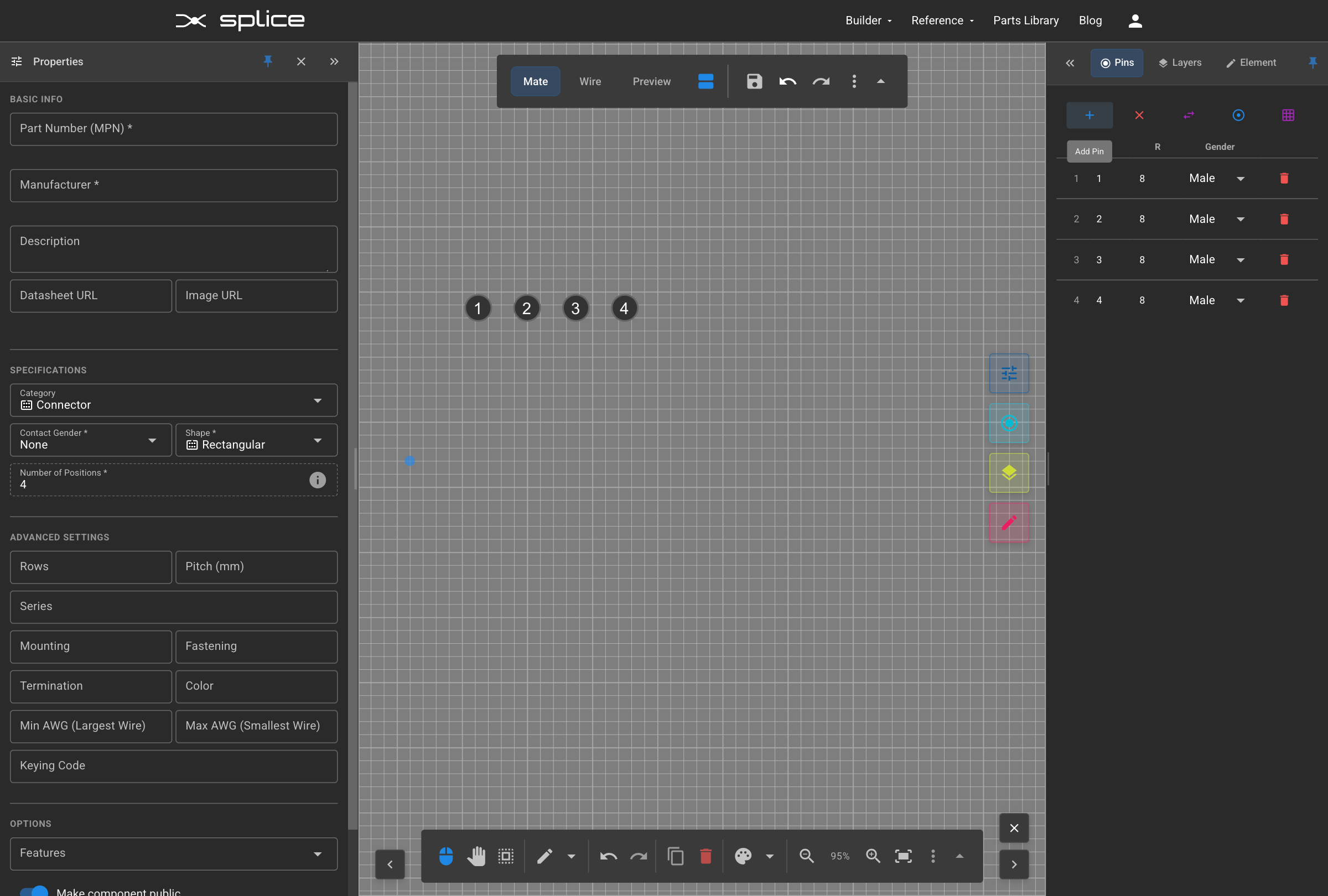
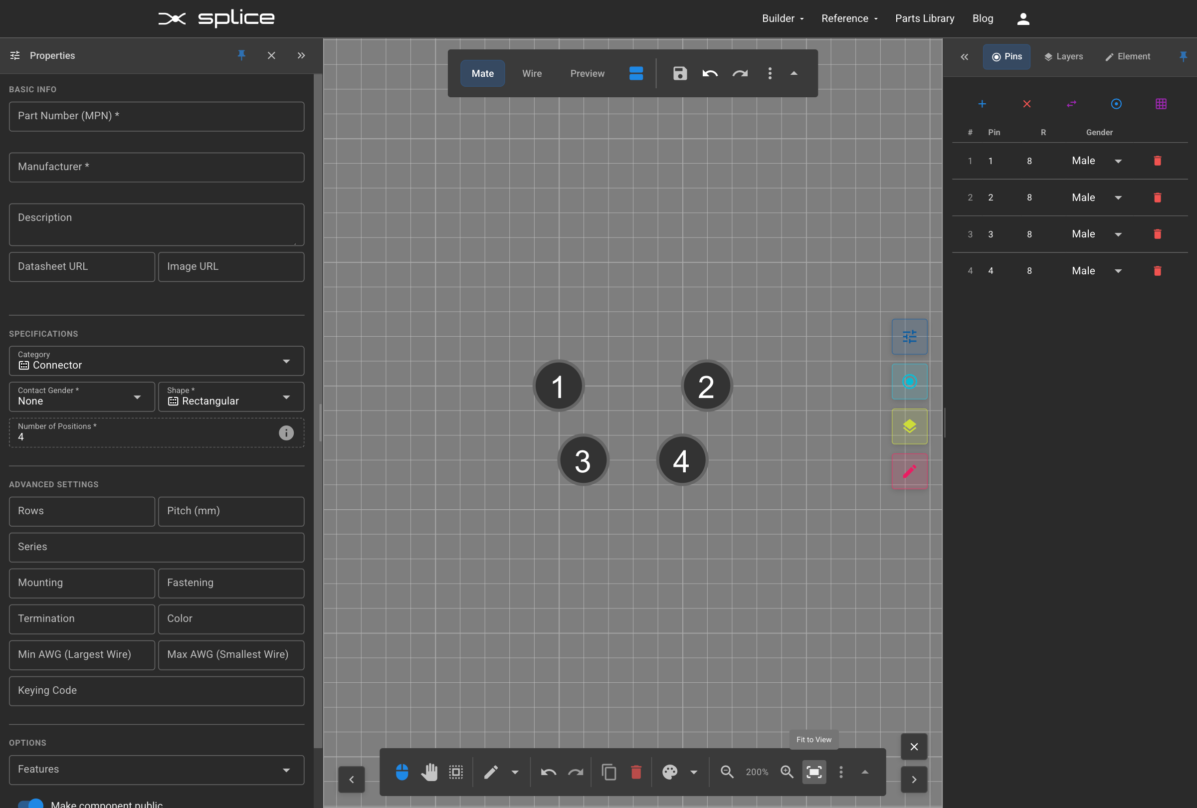
Adding Pins to Grid
Creating Pin Grid
Start by adding pins to define your connector's electrical contacts.
- Each pin gets automatically numbered starting from 1. You can edit the pin number (e.g., for M8 series connectors with 3 pins and pin labels 1, 3, 4) in the Pin Manager tab
- Pin positions are shown in real-time coordinates
Arranging Pins
Dragging Pin Positions
Once pins are placed, you can position them by dragging.
- Click and drag any pin to reposition it
- Use the grid for alignment assistance
- Pin coordinates update automatically as you drag
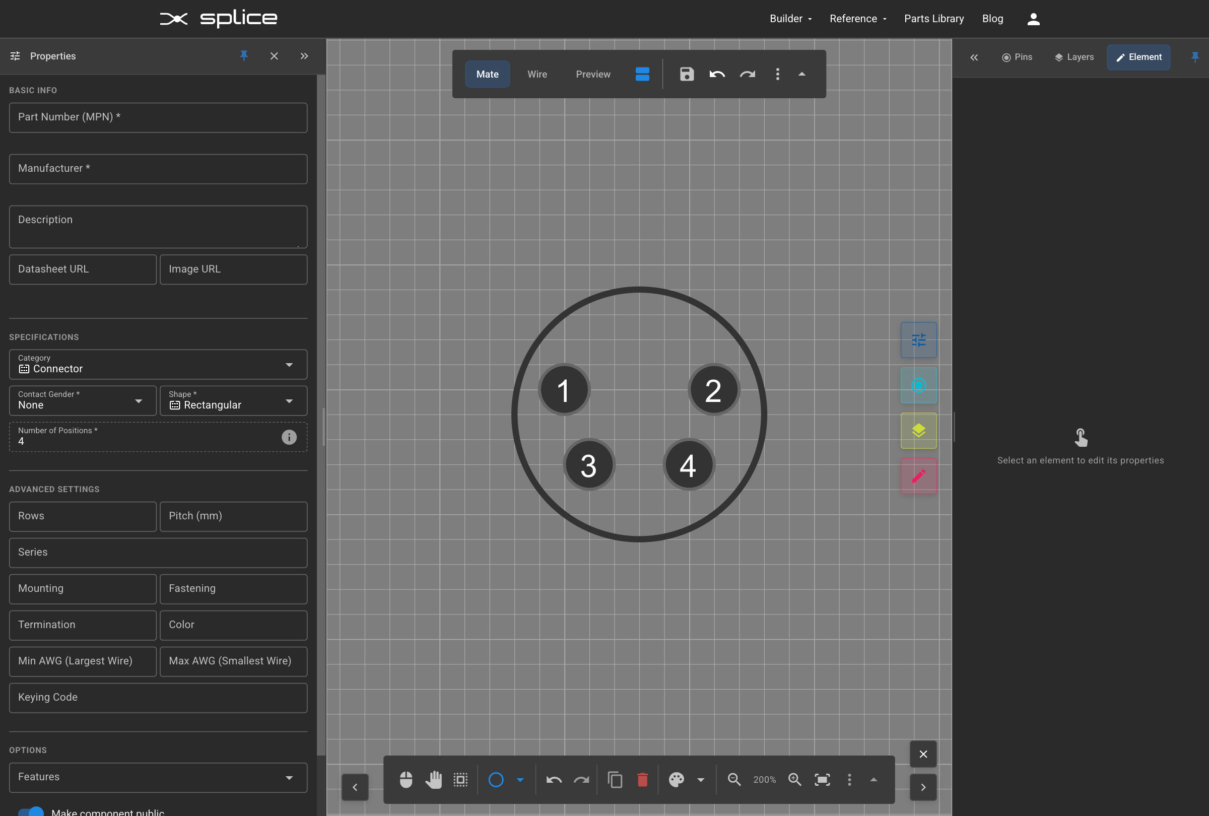
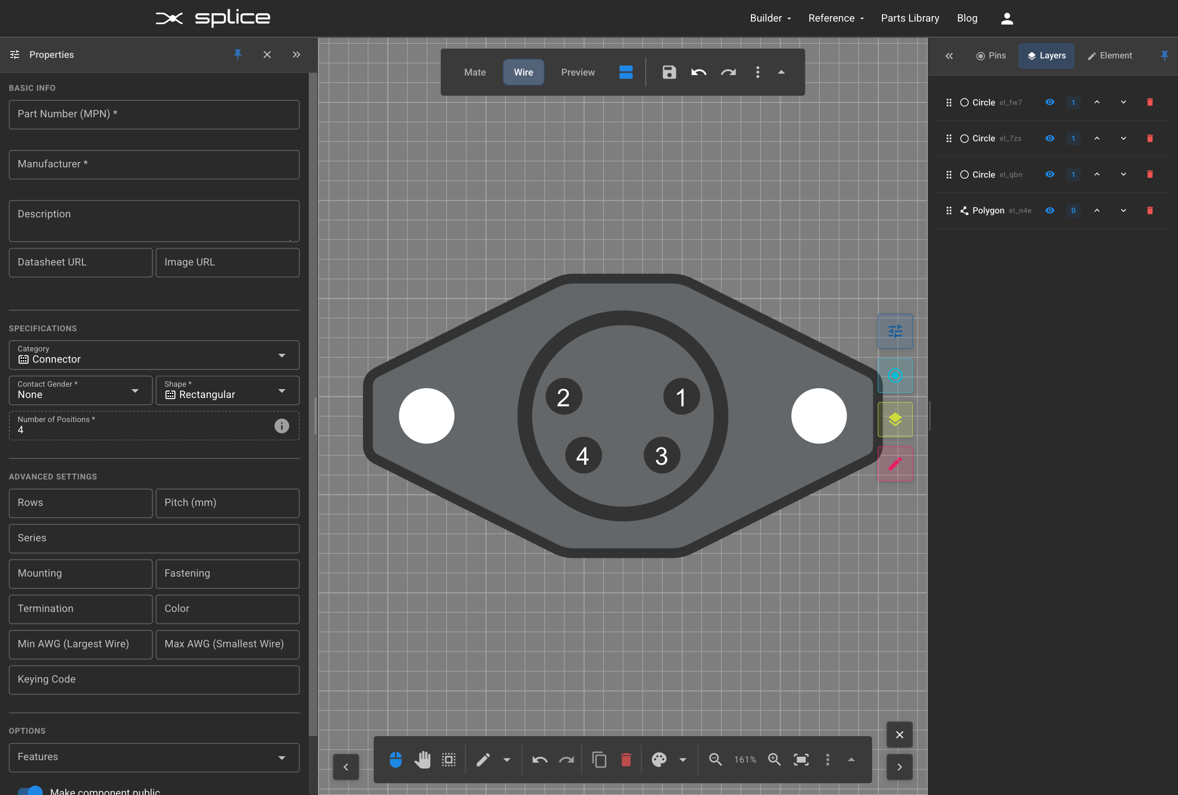
Final Pin Layout
Arrange the 4 pins in a pattern to match the physical connector's pin arrangement.
Adding Circle Outline
Drawing Pin Outlines
Add a circular outline around your pins to represent the mating receptacle on the connector.
- Select the Circle tool from the SVG toolbar
- Draw a circle around the pin pattern
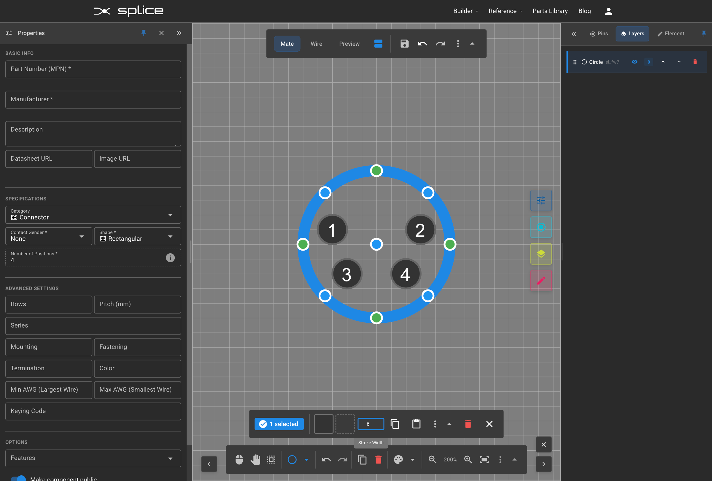
Changing Stroke Thickness
Adjusting Line Weight
Modify the stroke thickness of your circle to make them more visible and match the visual weight appropriate for your connector design.
- Select the circle you want to modify
- Adjust stroke weight in the properties panel
- Use thicker strokes for main outlines
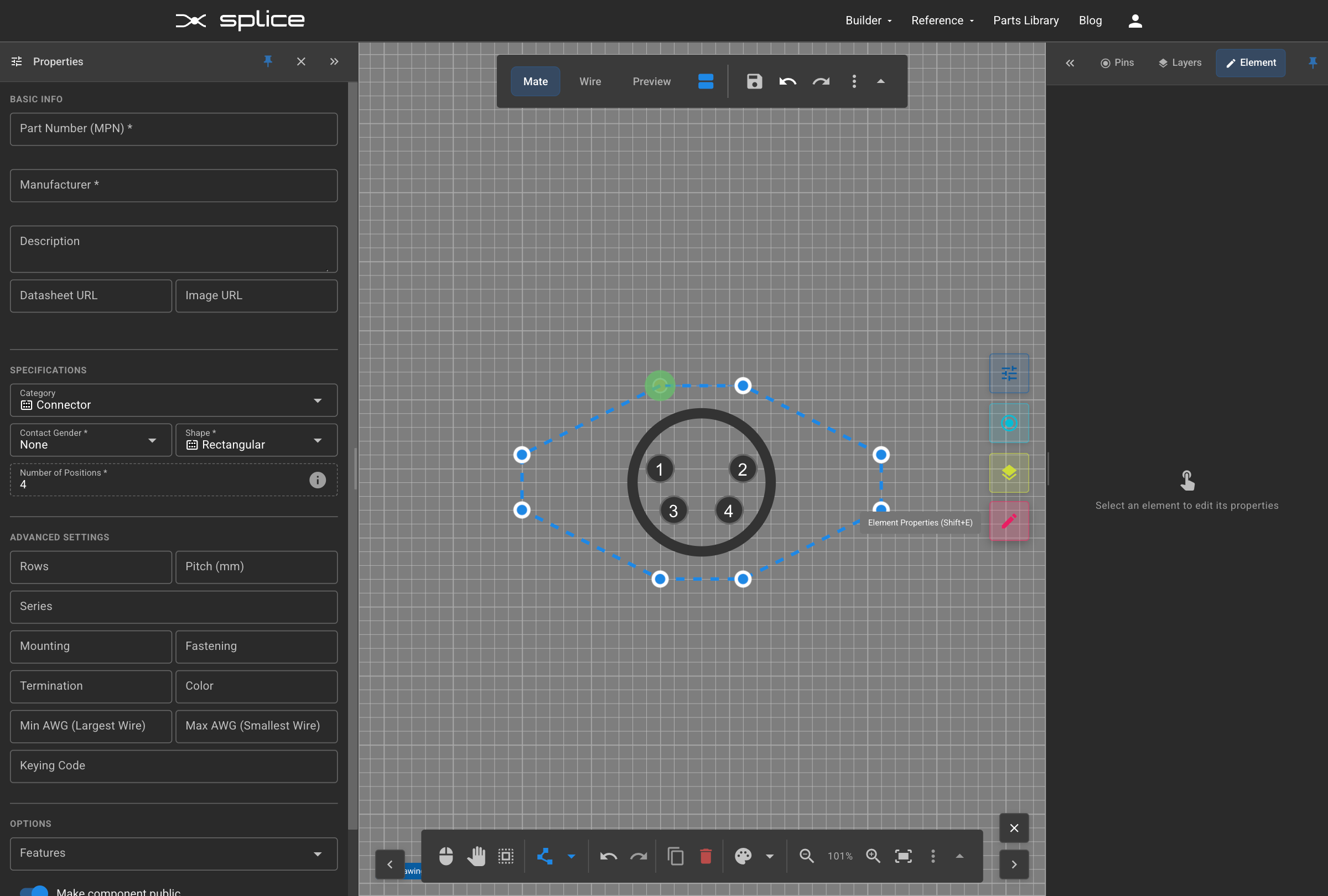
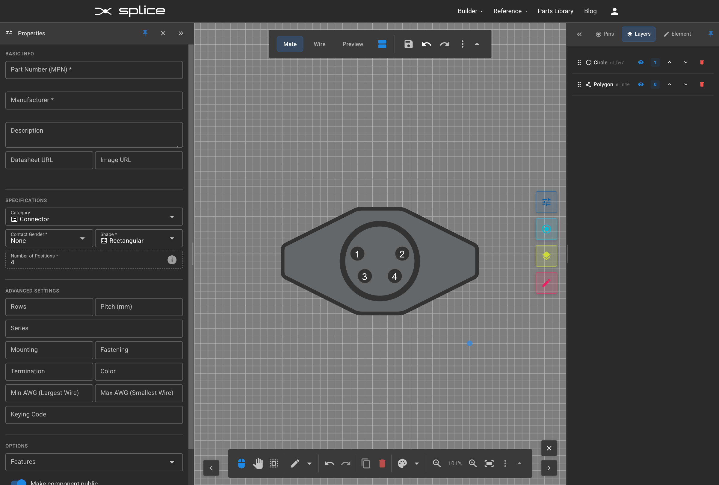
Adding Connector Outline
Drawing the Housing
Create the main connector housing outline that will contain all the pins.
- Use the Polygon tool for basic housing shapes
- Draw around the pin area with appropriate margins
- Leave space for mounting features if needed
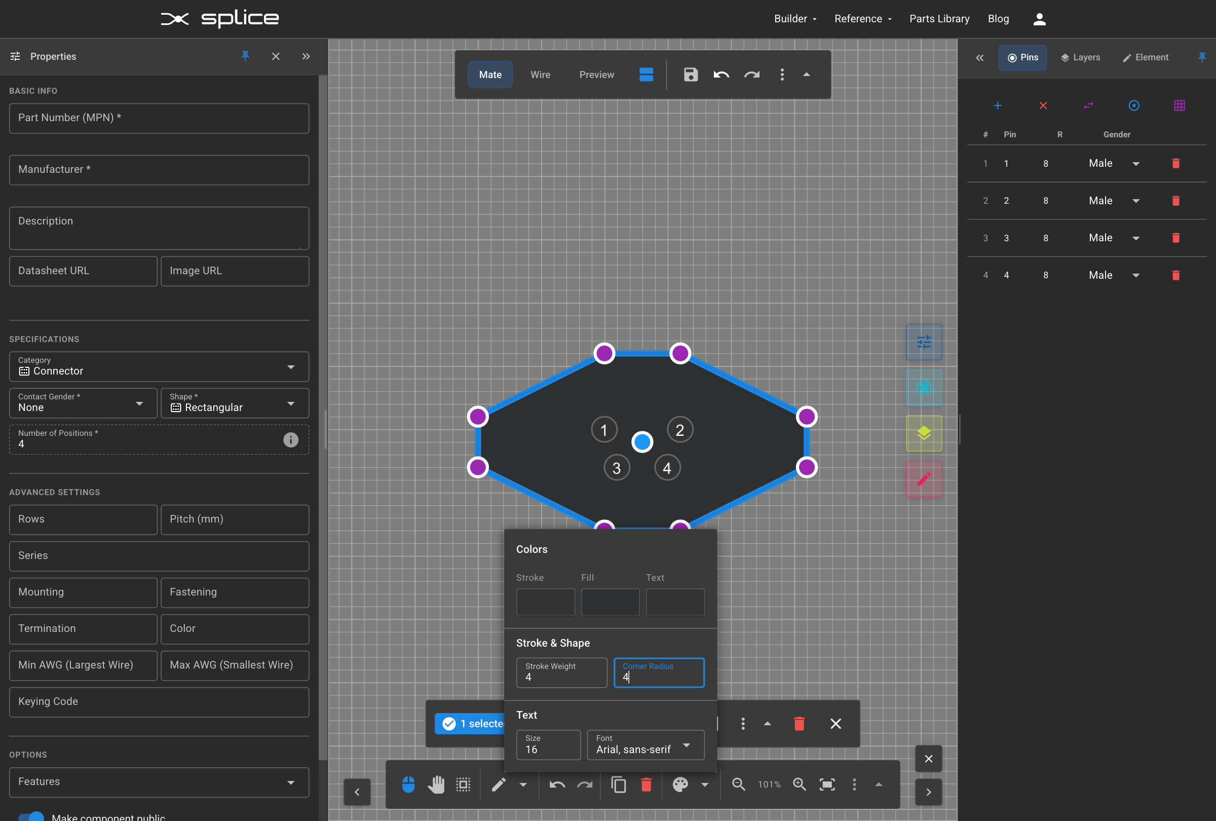
Corner Radius and Fill Color
Rounding Corners
Add rounded corners to your connector housing to create a more realistic and professional appearance.
- Select the housing rectangle
- Adjust corner radius properties
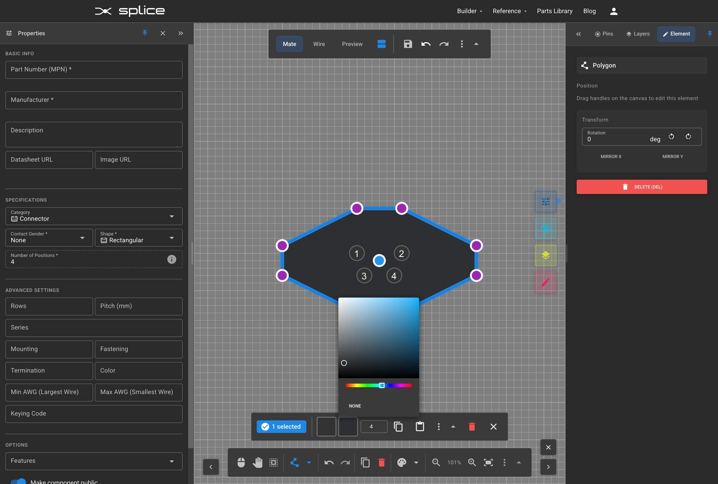
Housing Fill
Add a fill color to your connector housing to distinguish it from the background.
- Select the housing outline
- Choose an appropriate fill color
- Use neutral colors for realistic appearance
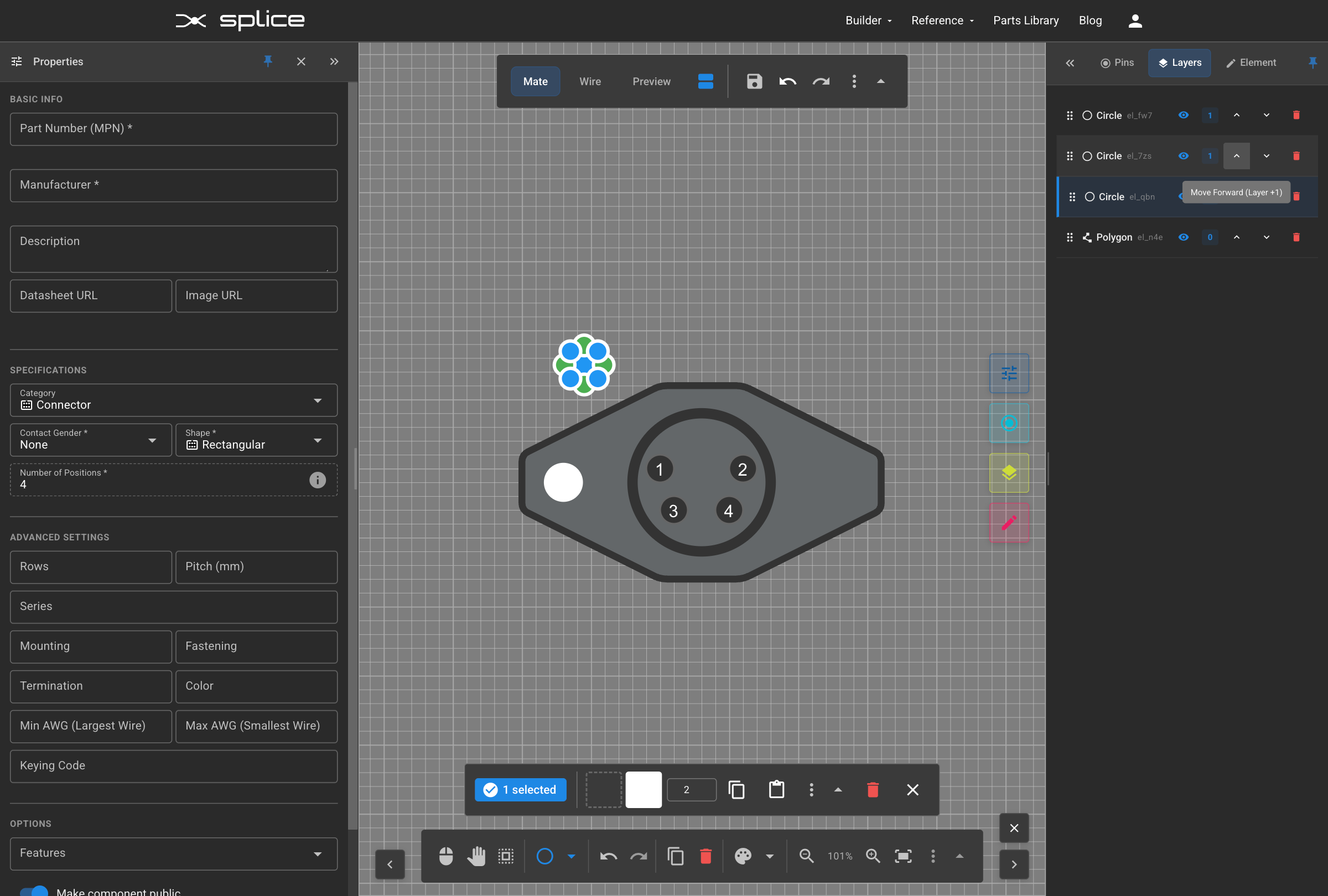
Changing Layer Order
Bringing Circles to Front
Adjust the layer order to ensure pin circles appear in front of the housing fill.
- Select the pin circles
- Use the arrows on the Layer Manager controls to increase the circles' layer number
- Ensure pins are visible above housing
Adding Mounting Holes
Creating Mounting Features
Add mounting holes or tabs to your connector design to show how it mechanically attaches or mounts in the application.
- Draw small circles for mounting holes
- Position them symmetrically around the housing
- Use appropriate size relative to the connector
- Consider real-world mounting requirements
Copy and Paste Features
Duplicating Elements
Use Ctrl+C and Ctrl+V to efficiently copy and paste elements like mounting holes.
- Select the element to copy (Ctrl+C)
- Paste with Ctrl+V to create a duplicate
- Position the copy in the desired location
Wire Side View
Viewing Wire Side
Switch to the Wire Side tab to see the automatically generated mirror view of your connector.
- Click the "Wire Side" tab
- View the mirrored version of your design
- Pin positions are automatically mirrored

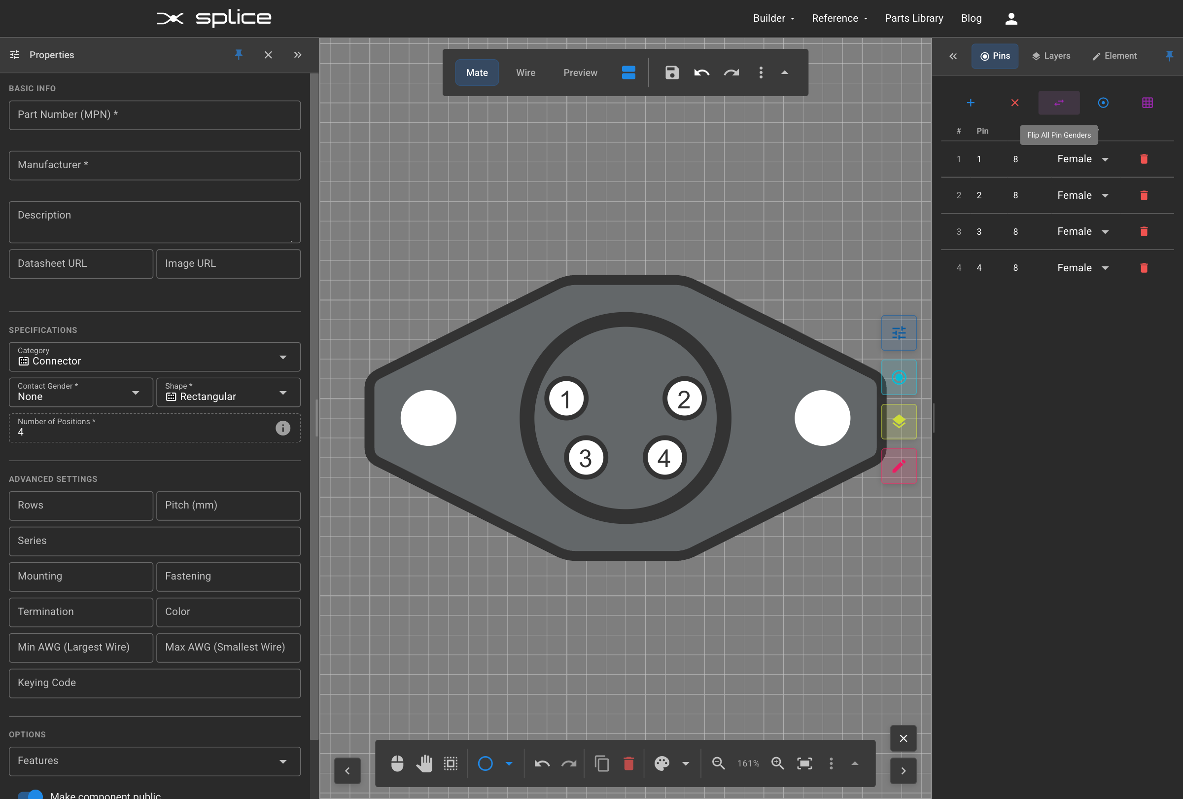
Changing Pin Gender
Flip All to Female
Change the pin gender from male to female using the "Flip All" button.
- Locate the "Flip All" button in the pin configuration
- Click to change all pins from male to female
- Pin representations update automatically
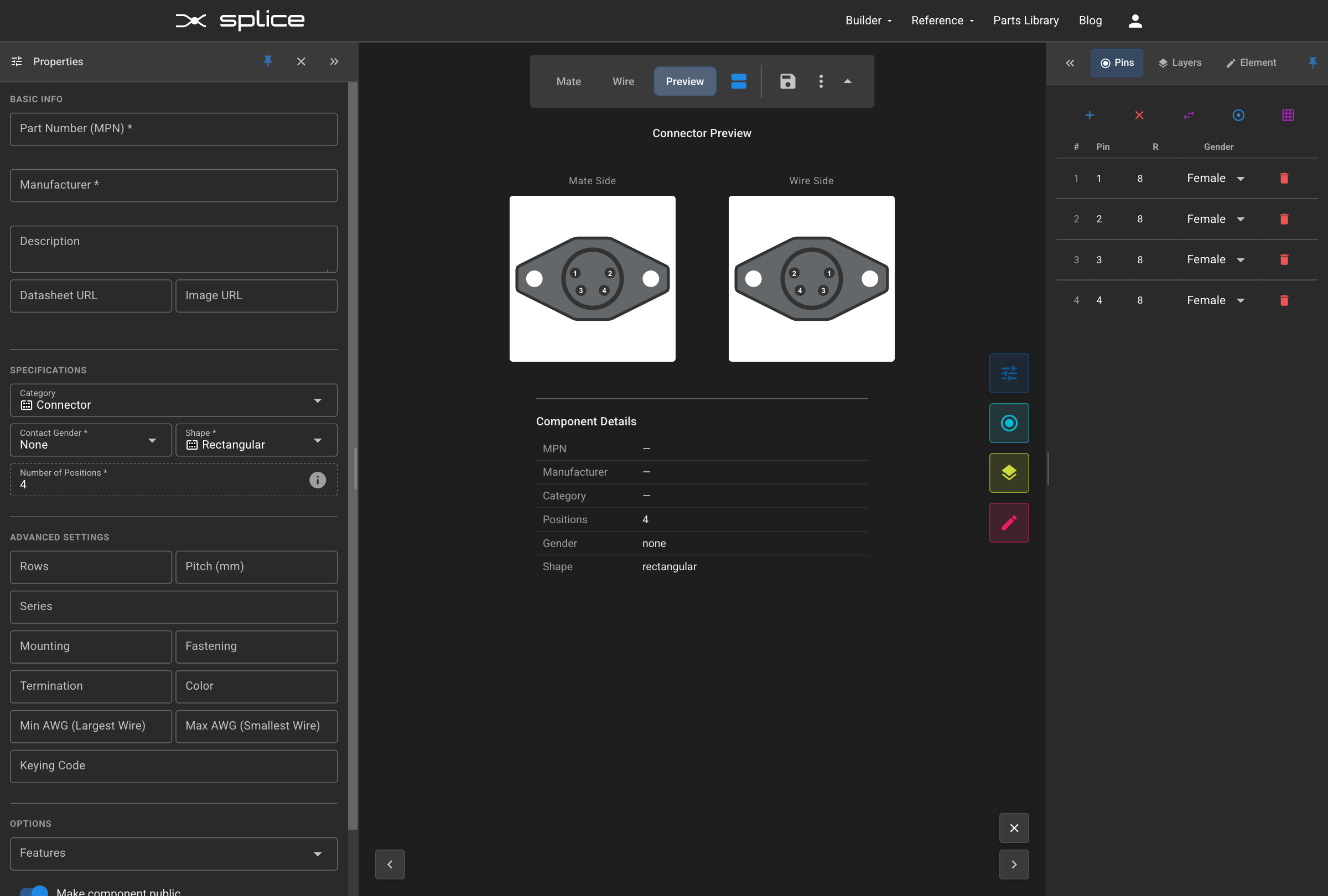
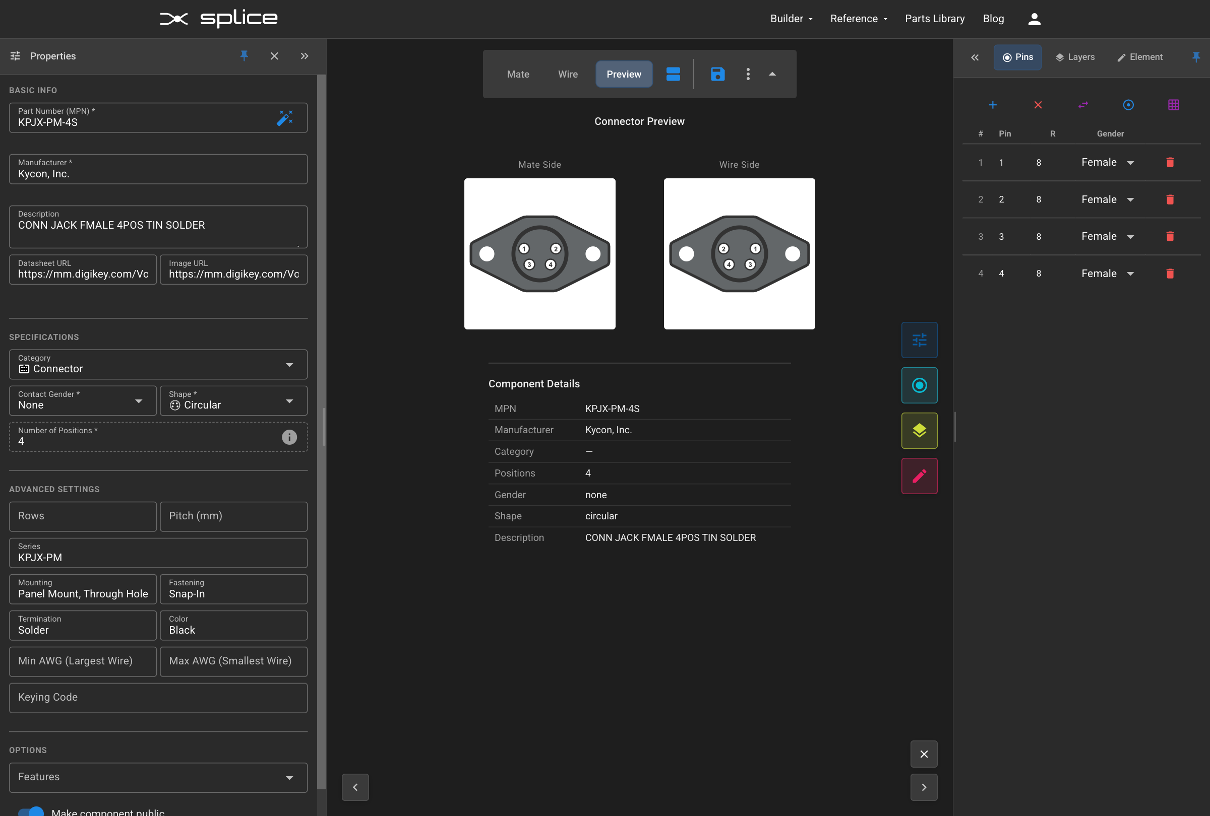
Preview Tab
Viewing Preview
Switch to the Preview tab to see both sides of your connector together.
- Click the "Preview" tab
- View both mate and wire sides simultaneously
- Verify pin alignment and numbering
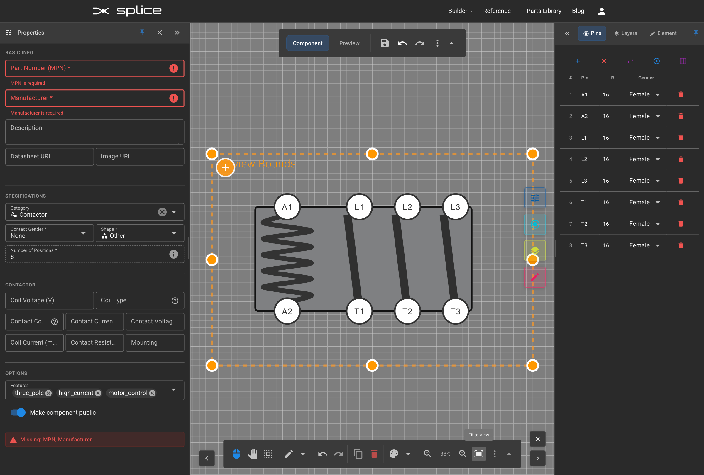
Manual Preview Bounds
Controlling Preview Region
Use manual preview bounds to control exactly which portion of your design appears in the preview and harness diagrams.
Setting Preview Bounds
- Click the "Manual Preview Bounds" button (crop icon) on the upper toolbar
- An orange dashed rectangle appears showing the preview region
- Drag the rectangle to reposition the preview area
- Resize using the corner and edge handles
- Wire side bounds automatically mirror mate side settings
Adding Properties
Connector Information
Fill in the basic properties like part number, manufacturer, and description to properly identify your custom connector.
- Enter the part number (MPN)
- Specify the manufacturer name
- Add a descriptive description
- Set technical specifications as needed
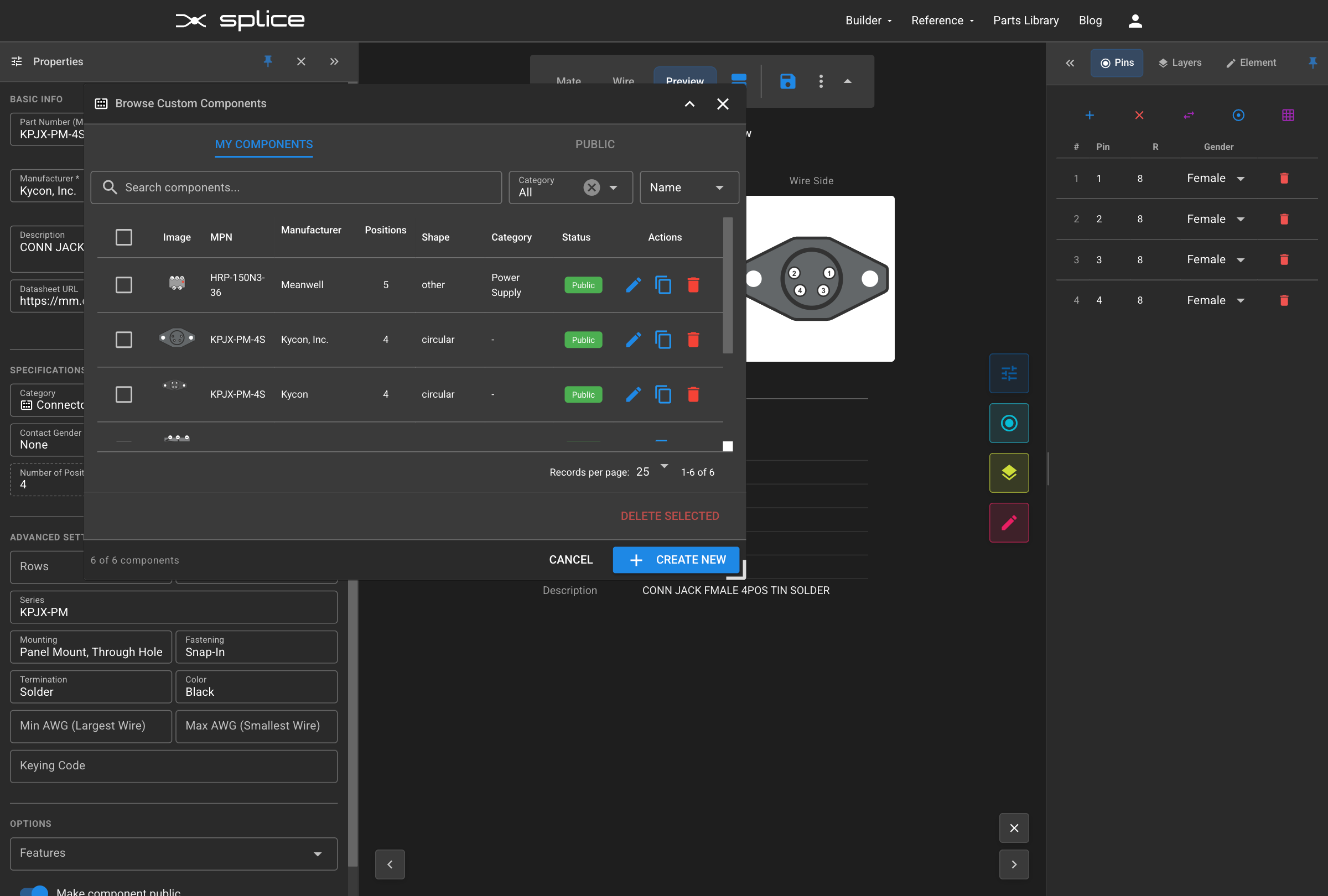
Saved Connector in Browse
Viewing Saved Connectors
After saving, your connector appears in the connector browser where you can load it for editing or use it in harness designs.
- Save your connector using the Create Connector button
- Open the Browse dialog to see saved connectors
- Your connector appears in the list
- Can be loaded for editing or used in harnesses
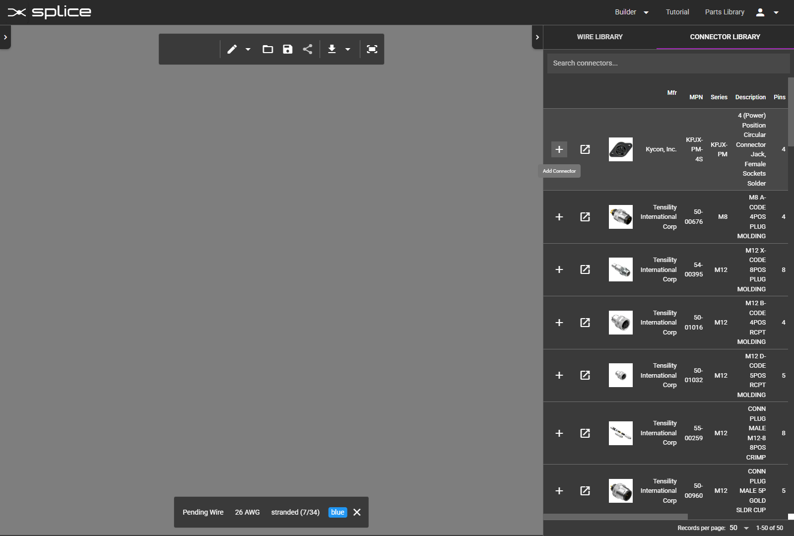
Adding to Harness
Using in Harness Builder
Navigate to the Harness Builder to use your custom connector in an actual cable harness design, just like any standard connector.
- Go to App → Assembly Builder
- Search for your custom connector in the parts library
- Add it to your harness like any other connector
- Your custom design appears on the canvas
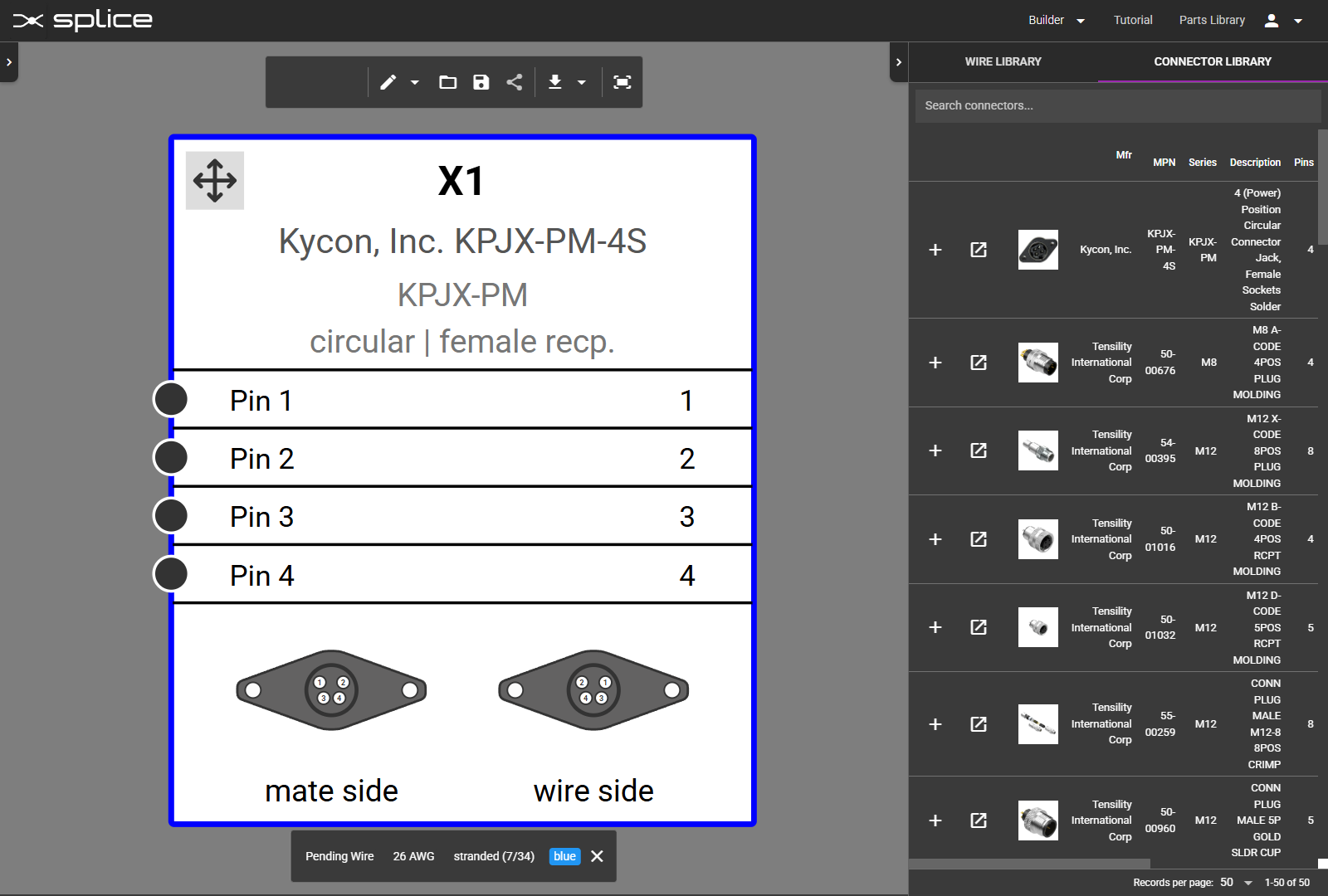
Connector in Harness
Custom Connector on Canvas
Your custom connector now appears on the harness canvas with your designed appearance and can be wired like any standard connector.
- Connector displays with your custom graphics
- All pins are available for wire connections
- Pin numbers match your design
- Works with all harness builder features
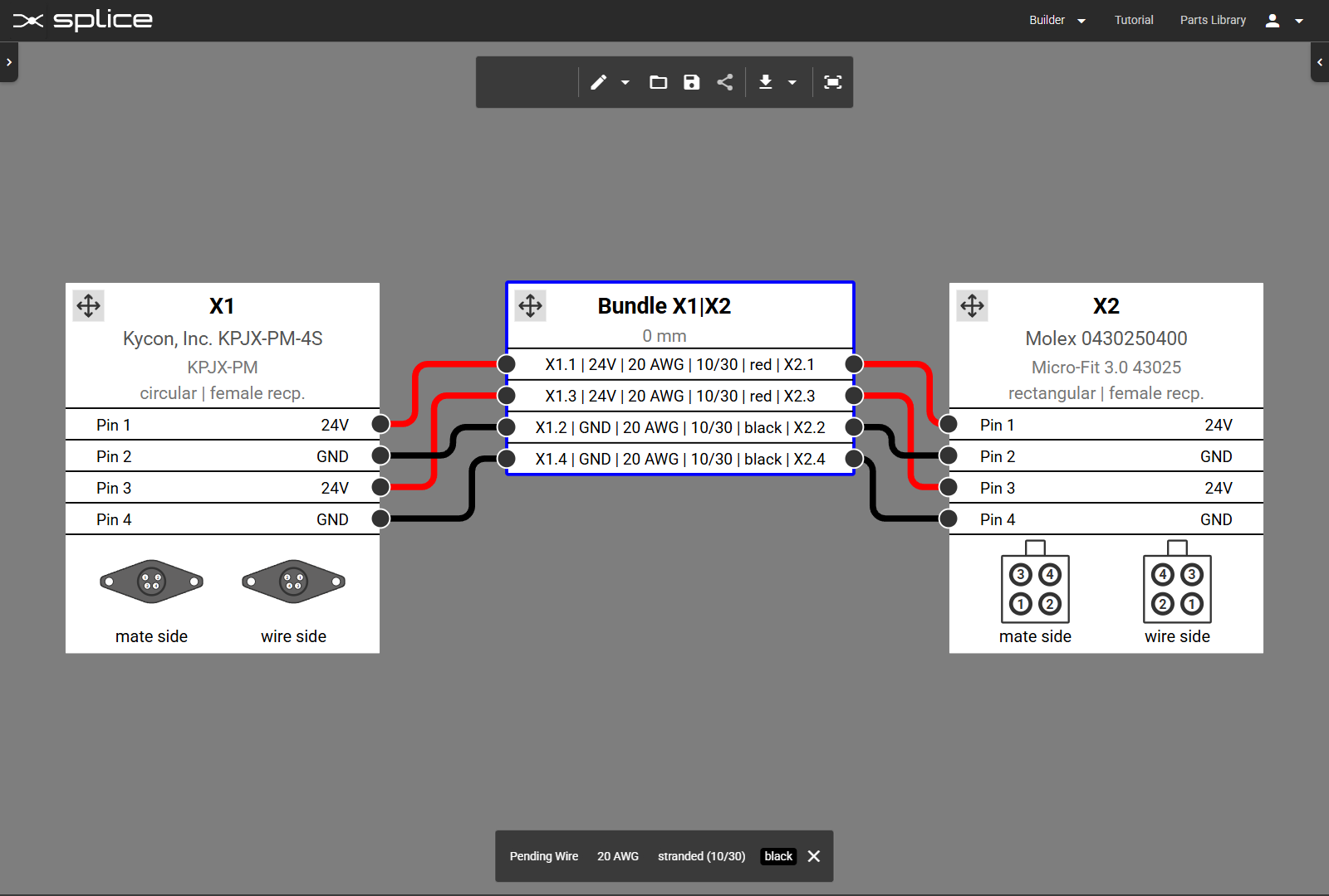
Wiring Connections
Making Wire Connections
Connect wires to your custom connector pins, demonstrating that it functions exactly like any standard connector in the library.
- Select a wire from the wire library
- Click on a pin to make the first connection
- Click on another connector or create a flying lead
- Verify that the BOM updates with your custom connector
Complete Integration
Fully Functional Custom Connector
Your custom connector is now fully integrated into Splice and ready for use in any harness design with complete functionality.
- Make wire connections to any pin
- Appears in bills of materials
- Included in exports and documentation
- Can be shared with team members