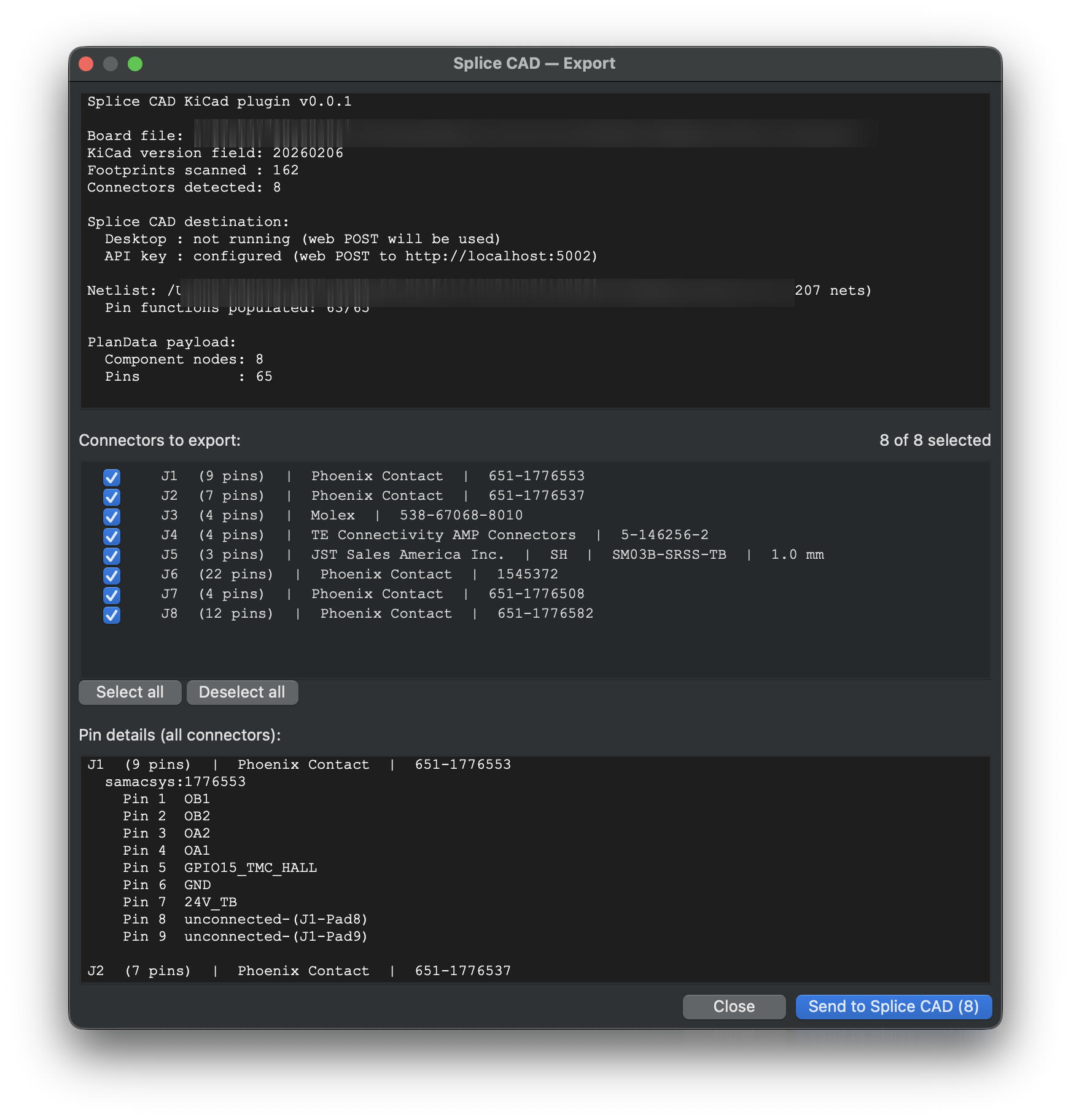
The Splice CAD KiCad plugin exports the connectors on your PCB into a Splice Project in one click — Tools → External Plugins → Export to Splice CAD. It detects each board header, reads pin functions from the netlist, and writes manufacturer/MPN to the BOM. Headers import into the Project Workflow as components; you assign the mating connectors and route conductors between them to complete the cable-harness document.
Details
- Detection: connectors by reference prefix (
J/CN/CON/P/X) and footprint pattern; mounting holes and non-plated pads filtered out. - Pin functions: read from the sibling
.netnetlist — signals (e.g.CAN_H) land on the correct pins; unconnected pins areNC. - Delivery: hands off to a running Splice CAD desktop app over localhost (offline, no API key), or POSTs to your account with an API key.
- Stable IDs: node/pin IDs derive from each connector reference, so re-export reproduces the same shape.
Install
In KiCad's Plugin and Content Manager → Manage → Repositories, add:
https://splice-cad.github.io/splice-kicad-plugin/repository.json
Install Splice CAD; it appears under Tools → External Plugins in the PCB Editor.
See the KiCad Plugin docs. Open source on GitHub (GPL-3.0).