KiCad Plugin
The Splice CAD KiCad plugin exports the connectors (board headers) on your PCB straight into a Splice Project — one click, Tools → External Plugins → Export to Splice CAD. It detects each header from the PCB, reads its pin functions from the netlist, and carries part metadata (MPN, manufacturer) into the BOM.
The headers land in the Project Workflow as components, each with its pin count and the correct signal on every pin. You then assign the mating connectors and route conductors between them to complete the cable-harness document.
The plugin delivers the project two ways, chosen automatically:
- Desktop handoff — if the Splice CAD desktop app is running, the plugin hands the project to it over localhost. Works offline; no API key needed.
- Web — otherwise it POSTs to your Splice account using your API key, creates a Project, and gives you a link to open it in the Project Editor.
1. Install
The plugin is distributed through KiCad’s Plugin and Content Manager (PCM).
From the Splice repository (recommended — auto-updates)
-
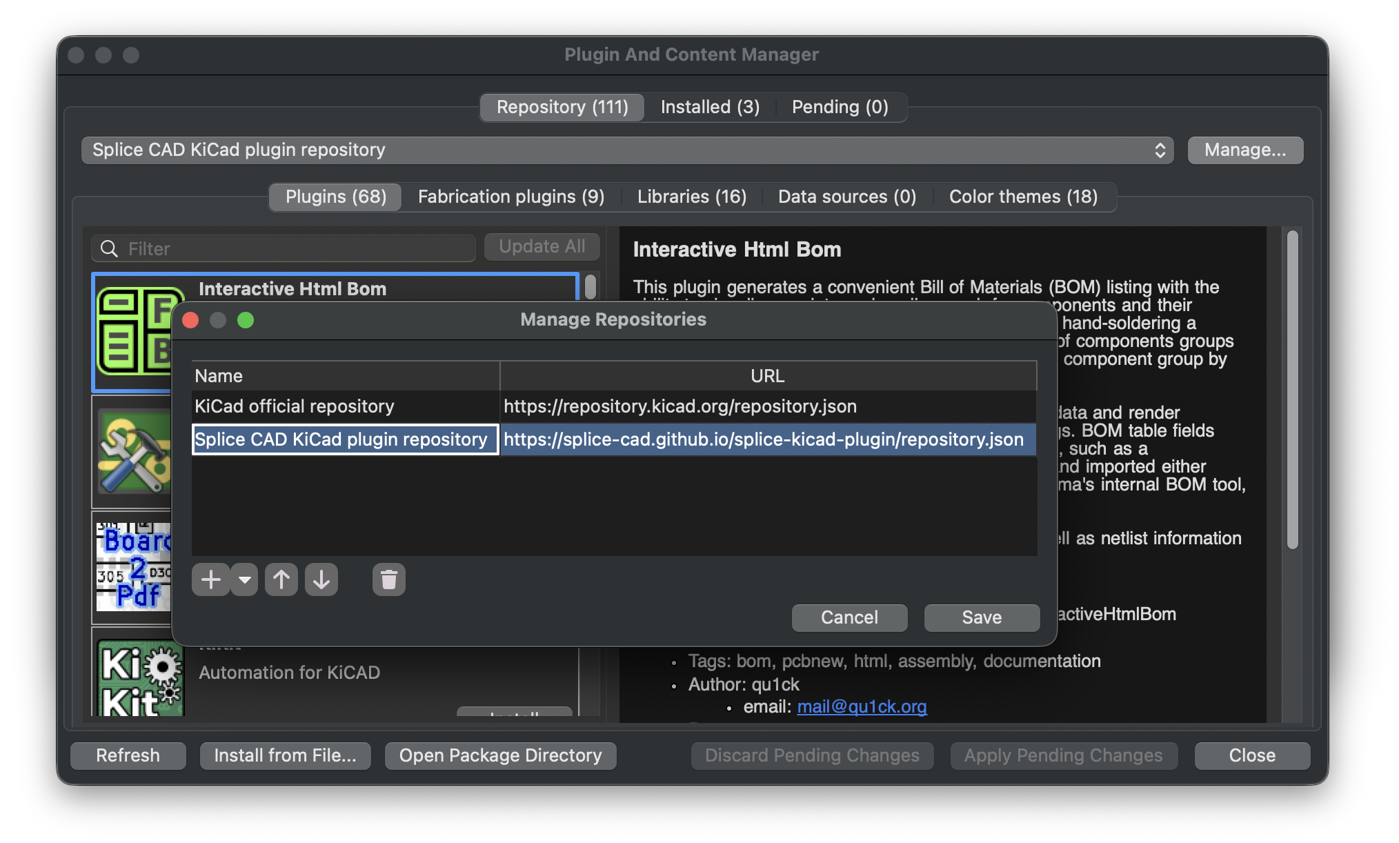
KiCad → Plugin and Content Manager → Manage (top-right) → Repositories.
-
Add this URL (name it “Splice CAD”):
https://splice-cad.github.io/splice-kicad-plugin/repository.json -
Back in the PCM, pick Splice CAD from the repository dropdown.
-
Select Splice CAD → Install → Apply Pending Changes.
From a file
Download splice-kicad-plugin-<version>.zip from Releases and use Plugin and Content Manager → Install from File.
After installing, open the PCB Editor — you’ll find Export to Splice CAD and Splice CAD — Settings under Tools → External Plugins. (If they don’t appear, see Troubleshooting.)
Requirements: KiCad 9.0 or newer (the plugin runs in the PCB Editor). It uses KiCad’s bundled Python 3.9+.
2. Set up (Settings)
Open Tools → External Plugins → Splice CAD — Settings.
| Field | Description |
|---|---|
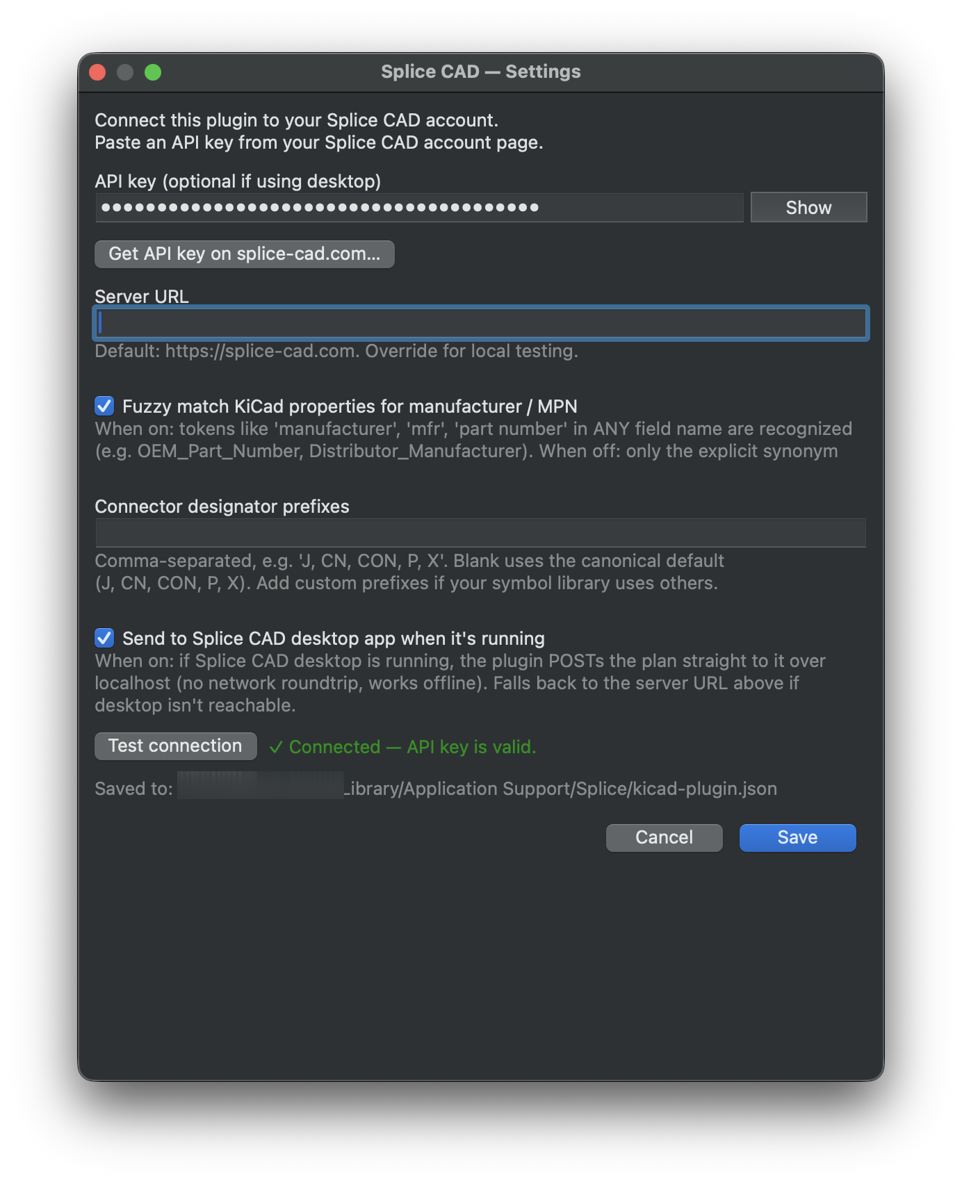
| API key | Your Splice CAD API key — Get API key on splice-cad.com… opens your account page. Used for the web send path; optional if you only send to the running desktop app. |
| Server URL | Splice backend. Default https://splice-cad.com; override only for local testing. |
| Fuzzy match KiCad properties for manufacturer / MPN | When on, tokens like manufacturer / mfr / part number in any field name are recognized (e.g. OEM_Part_Number); when off, only the explicit synonyms. |
| Connector designator prefixes | Comma-separated (e.g. J, CN, CON, P, X). Blank uses the default J, CN, CON, P, X; add custom prefixes if your library uses others. |
| Send to Splice CAD desktop app when it’s running | When on, POSTs to the desktop app over localhost (offline, no network roundtrip); falls back to the Server URL if the desktop isn’t reachable. |
Test connection validates the key + server before exporting.
3. Export a design
- Open your board in the PCB Editor and make sure it’s saved.
- Tools → External Plugins → Export to Splice CAD.
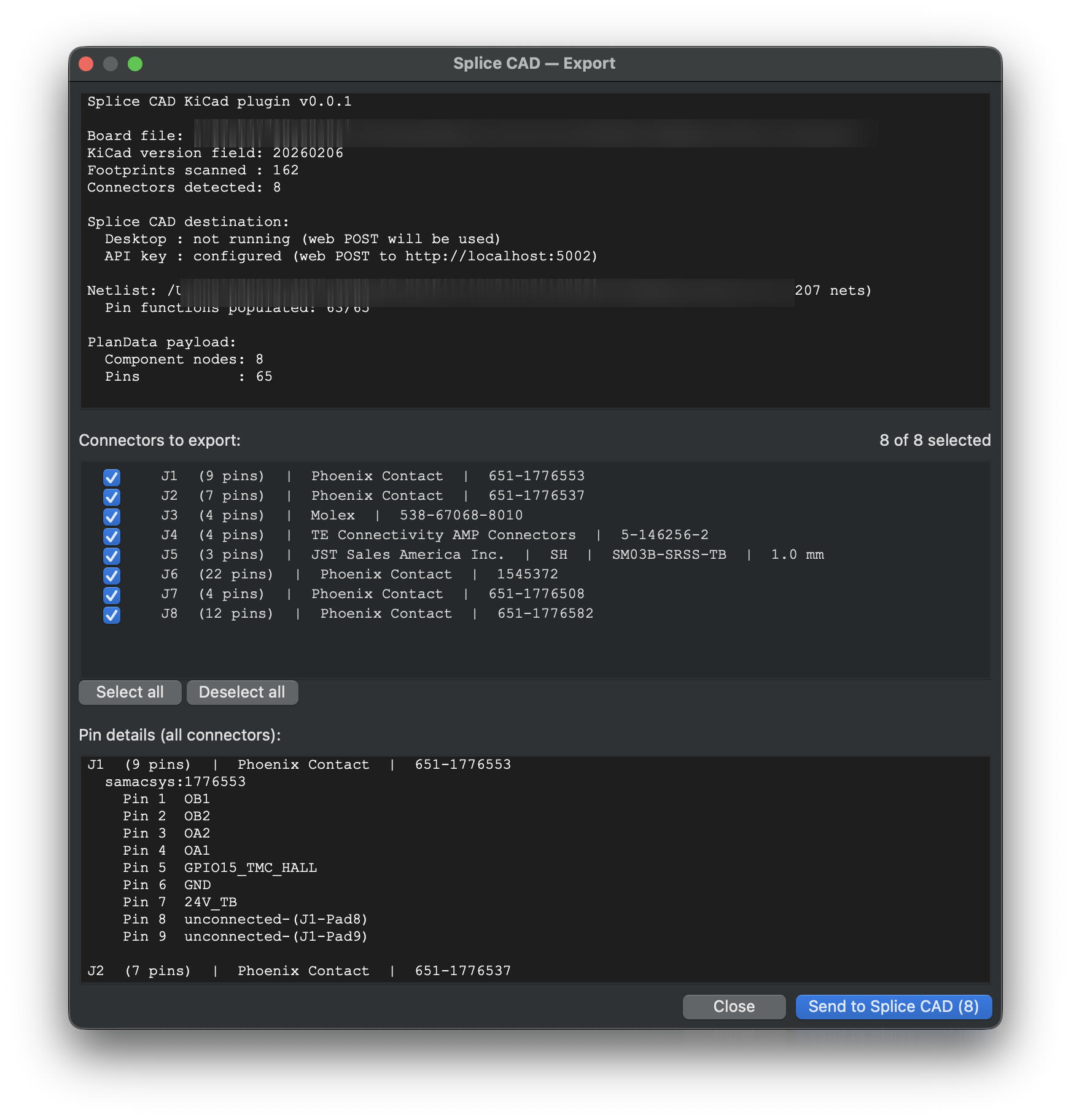
- The preview dialog shows:
- a board summary (connectors, pins, and how the netlist resolved),
- the send path that will be used (desktop or web),
- a per-connector list with footprint, MPN, pin count, and the full pin table,
- a checkbox per connector so you can deselect anything you don’t want exported.
- Click Send. On success you get an Open in Splice CAD action that takes you straight to the new Project in the Project Editor.
The board headers land as components on an auto-arranged grid (Splice’s Auto-arrange can re-flow them), each with its pins and net-derived signals. From here you complete the cable-harness document in the Project Workflow: resolve each header to a catalog part, add the mating connector that plugs into it, and route conductors between them.
4. What gets imported
Board connectors (headers). Detected from the PCB by reference prefix (J, CN, CON, P, X) and footprint name (JST, Molex, TE, Hirose, Phoenix, and generic header/socket/plug patterns). Mounting holes and non-plated pads (MP*, MH*, MTG*, np_thru_hole) are filtered out. These are the board-side interface — the components you’ll assign mating connectors to.
Pins and pin functions. Each connector pad becomes a pin. If a netlist (<project>.net) sits next to the board, each pin is labelled with the net it carries — so J1.3 and J7.12 on CAN_H both show CAN_H. Unconnected pins show NC.
To get pin functions, export a netlist. In the Schematic Editor: File → Export → Netlist → KiCad (S-expression), saved next to your board as
<project>.net. Without it, pins import with numbers only.
Part metadata → BOM. Manufacturer and MPN are pulled from the symbol/footprint properties (a long synonym list — MPN, Mfr_PN, Manufacturer_Part_Number, …) and written to the Splice BOM so you can resolve catalog parts after import. The KiCad project name becomes the Splice project name.
Stable IDs. Node and pin IDs are derived from each connector’s reference, so re-exporting the same project produces the same shape.
What you do in Splice’s Project Workflow after import: resolve each header to a catalog part, add the mating connector for each one, route conductors between header and mate, and set wire colors/gauges — completing the cable-harness document. (The plugin imports only the board-side headers; it doesn’t invent the mating side or the wiring.)
Troubleshooting
- Menu entry / icon doesn’t appear after install. Tools → External Plugins → Refresh Plugins, or restart KiCad. The plugin lives in the PCB Editor, not the Schematic Editor.
- “No board file is open.” Save the board first — the plugin reads the saved
.kicad_pcb. - No connectors detected. Your connectors may use non-standard reference prefixes. Use one of
J / CN / CON / P / X, or a recognized connector footprint. - Pins import without functions (all NC). No netlist was found next to the board — export
<project>.netfrom the Schematic Editor (see above). - “Send” is disabled. Neither path is available: the desktop app isn’t running and no API key is configured. Start the desktop app, or add an API key in Settings.
- Re-exporting makes a new project each time. Expected in the current release — match-and-update on re-export is planned. For now, re-import replaces by opening the newest plan.
Source
The plugin is open source (GPL-3.0) at splice-cad/splice-kicad-plugin. Issues and contributions welcome.